| Python Exemplary |
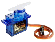
SERVOMOTORS
![]()
The source code of all examples can be downloaded from here.
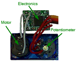
How servomotors work |
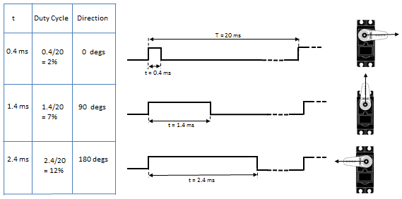
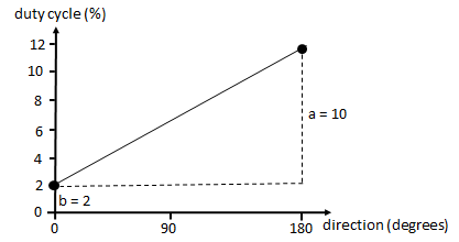
Many servomotors use a PWM frequency of fPWM = 50 Hz corresponding to a PWM period of T = 20 ms. The relationship between the pulse length t and the direction is linear and depends on the motor and the gear Example:
Servo motors are widely used in radio-controlled toys (cars, airplanes, etc.), but also in industrial applications where a precise rotation position is needed (e.g. in robotics). An alternative (and often better solution) to achieve direction control is the stepper motor (see next tutorial). |
|||||||||
|
|
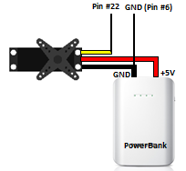
Experiment 1: Motor directly connected to the GPIO |
|
Aim:
Connect the brown (or black wire) to GND (pin #6), the red wire to 5 V (pin #2) and the yellow wire to any GPIO output. The servomotor is powered by 5 V, but controlled by 3.3 V. Program:[►] # Servo1.py import RPi.GPIO as GPIO import time P_SERVO = 22 # adapt to your wiring fPWM = 50 # Hz (not higher with software PWM) a = 10 b = 2 def setup(): global pwm GPIO.setmode(GPIO.BOARD) GPIO.setup(P_SERVO, GPIO.OUT) pwm = GPIO.PWM(P_SERVO, fPWM) pwm.start(0) def setDirection(direction): duty = a / 180 * direction + b pwm.ChangeDutyCycle(duty) print "direction =", direction, "-> duty =", duty time.sleep(1) # allow to settle print "starting" setup() for direction in range(0, 181, 10): setDirection(direction) direction = 0 setDirection(0) GPIO.cleanup() print "done" Remarks:
|
|
|
Experiment 2: Servomotors driven by the PCA9685 |
|
Generating stable PWM signals by software is a heavy burden for a microprocessor running Linux, because there are other processes running on the system that may interrupt the PWM generating code. It is a better solution to use a special purpose external chip that does the job, especially if you need several PWM signals.
Aim: On order to simplify your programming task, use a small library PCA9685.py inspired by the Adafruit PWM Servo Driver (download here and copy in same directory with your program). Program:[►] # Servo2.py # Two servo motors driven by PCA9685 chip from smbus import SMBus from PCA9685 import PWM import time fPWM = 50 i2c_address = 0x40 # (standard) adapt to your module channel = 0 # adapt to your wiring a = 8.5 # adapt to your servo b = 2 # adapt to your servo def setup(): global pwm bus = SMBus(1) # Raspberry Pi revision 2 pwm = PWM(bus, i2c_address) pwm.setFreq(fPWM) def setDirection(direction): duty = a / 180 * direction + b pwm.setDuty(channel, duty) print "direction =", direction, "-> duty =", duty time.sleep(1) # allow to settle print "starting" setup() for direction in range(0, 181, 10): setDirection(direction) direction = 0 setDirection(0) print "done" Remarks: |
|
|
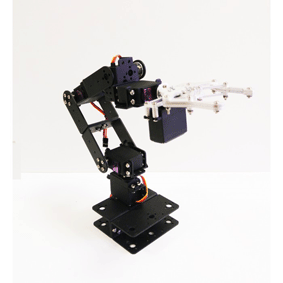
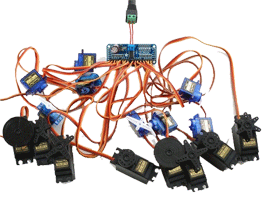
Experiment 3: A robot arm with six degrees of freedom |
|
A robot arm has a number of degrees of freedom to move in any desired position. To control the position precisely, servomotors (or stepper motors) are widely used. Aim:
(to be done) |