RaspEasy
EXPERIMENTAL MODULE
(by Didel)
RaspEasy
|
|
![]()
The source code of all examples can be downloaded from here.
Preliminary: This chapter can be used as independent introduction to sensor technology.
It contains some duplicated exercises from other chapters.
Introduction |
|
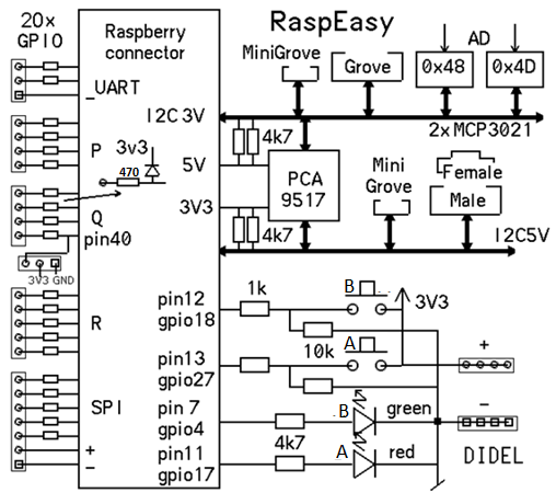
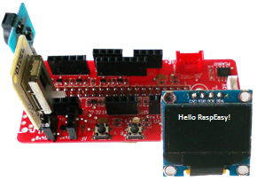
In the previous chapters you learned how to wire and connect electronics parts to the Raspberry Pi, mostly using a breadboard. In principle the circuits were simple, but the Raspberry Pi can easily be damaged by small inattention (e.g. by applying more than 3.3V to a GPIO pin). Moreover you need to provide every electronic parts as single unit (buttons, LEDs, etc). To simplify basic experiments with the Raspberry Pi, we recommend to use a cheap, but well-thought-out add-on board by Didel, called RaspEasy. Simply insert the module into the 40-pin GPIO header and you are ready to go for funny and instructive programming adventures without the need to worry about connecting wires. Source of supply:
Functional diagram:
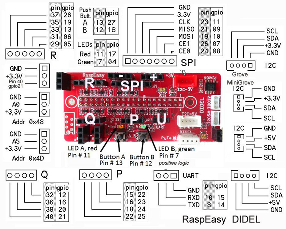
Header layout:
|
Experiment 1: Use a GPIO port as digital input or as digital output |
Aim: Program: [►] # RaspEasy1.py # Button press/release to switch on/off LED import RPi.GPIO as GPIO P_BUTTON = 12 # Button A #P_BUTTON = 13 # Button B P_LED = 7 # LED A #P_LED = 11 # LED B def setup(): GPIO.setmode(GPIO.BOARD) GPIO.setup(P_BUTTON, GPIO.IN) GPIO.setup(P_LED, GPIO.OUT) print "starting..." setup() while True: if GPIO.input(P_BUTTON) == GPIO.HIGH: GPIO.output(P_LED, GPIO.HIGH) else: GPIO.output(P_LED, GPIO.LOW) Remarks: In the example above, the state of the input pin is read ("scanned" or "polled") in a endless loop. The program is terminated by finishing the Python process. This is not a clean program termination because GPIO.cleanup() is never called. So some GPIO setups and states may survive until the next Python script invocation. Normally there is no harm in doing so. If you want to do better, have a look at experiment 4. |
|
|
Experiment 2: Button counter, contact bouncing |
|
Aim: It's easy, isn't it? You simply adapt the program above and increase the counter when the button is pressed. Program: [►] # RaspEasy2.py # Button counter import RPi.GPIO as GPIO P_BUTTON = 12 # Button A def setup(): GPIO.setmode(GPIO.BOARD) GPIO.setup(P_BUTTON, GPIO.IN) print "starting..." setup() count = 0 while True: if GPIO.input(P_BUTTON) == GPIO.HIGH: count += 1 print count Remarks: Best you consider the system as a state machine: There are two states: button-up and button-down. Only when the state changes from button-up to button-down the counter has to be increased. It is easy to handle the state by introducing a variable isButtonPressed that can be True or False (a so-called boolean variable). So your next attempt is the following: Program: [►] # RaspEasy2a.py # Button counter, 2nd attempt import RPi.GPIO as GPIO P_BUTTON = 12 # Button A def setup(): GPIO.setmode(GPIO.BOARD) GPIO.setup(P_BUTTON, GPIO.IN) print "starting..." setup() count = 0 isButtonPressed = False while True: if GPIO.input(P_BUTTON) == GPIO.HIGH and not isButtonPressed: isButtonPressed = True count += 1 print count elif GPIO.input(P_BUTTON) == GPIO.LOW and isButtonPressed: isButtonPressed = False Remarks:
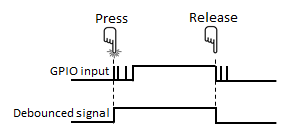
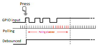
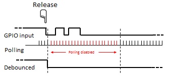
You can experience switch bouncing in your experimental setup, escpecially while opening the contact. In your counting application is absolutely mandatory to eliminate switch bouncing. But how to do it? You have two options: Either you add some extra electronics (actually a RS flip-flop or an RC-debouncer, search the Internet to inform you) or you do it by software. With software the idea to eliminate bouncing effects is the following:
Program: [►] # RaspEasy2b.py # Button counter, 3rd attempt import RPi.GPIO as GPIO import time P_BUTTON = 12 # Button A def setup(): GPIO.setmode(GPIO.BOARD) GPIO.setup(P_BUTTON, GPIO.IN) print "starting..." setup() count = 0 isButtonPressed = False while True: if GPIO.input(P_BUTTON) == GPIO.HIGH and not isButtonPressed: isButtonPressed = True count += 1 print count time.sleep(0.1) elif GPIO.input(P_BUTTON) == GPIO.LOW and isButtonPressed: isButtonPressed = False time.sleep(0.1) Remarks: As you see, we added the delay in the if and elif block. Is it not more elegant to put it once in the while block? This would work, but it is not completely equivalent, because a delay in the while block will be executed each time the loop is run, even in the "idle state" when the button is scanned to be pressed. So a short button hit that lasts less the 100 ms may be missed. As you see, even the simple handling of a button requires a lot of computational thinking. To get a standalone application you can display the counter value on an Oled or a 7-segment display. Program: [►] # RaspEasy2c.py # Button counter, use Oled or PyTell display import RPi.GPIO as GPIO import time from OLED1306 import OLED1306 #from pytell import PyTell P_BUTTON = 12 # Button A def setup(): GPIO.setmode(GPIO.BOARD) GPIO.setup(P_BUTTON, GPIO.IN) print "starting..." oled = OLED1306() oled.setFontSize(50) #pyTell = PyTell() setup() count = 0 oled.setText(str(count)) # pyTell.showText("%4d" %count) isButtonPressed = False while True: if GPIO.input(P_BUTTON) == GPIO.HIGH and not isButtonPressed: isButtonPressed = True count += 1 oled.setText(str(count)) # pyTell.showText("%4d" %count) time.sleep(0.1) elif GPIO.input(P_BUTTON) == GPIO.LOW and isButtonPressed: isButtonPressed = False time.sleep(0.1) Remarks: As you see, you must import either the OLED1306.py or the pytell.py module that you find in the code distribution. |
|
|
Experiment 3: LED state switcher |
|
Aim: Program: [►] # RaspEasy3.py # LED switcher import RPi.GPIO as GPIO import time P_BUTTON = 12 # Button A P_LED = 7 # LED A def setup(): GPIO.setmode(GPIO.BOARD) GPIO.setup(P_BUTTON, GPIO.IN) GPIO.setup(P_LED, GPIO.OUT) GPIO.output(P_LED, GPIO.LOW) # Turn off LED print "starting..." setup() isLedOn = False isButtonPressed = False while True: if GPIO.input(P_BUTTON) == GPIO.HIGH and not isButtonPressed: isButtonPressed = True if isLedOn: isLedOn = False GPIO.output(P_LED, GPIO.LOW) else: isLedOn = True GPIO.output(P_LED, GPIO.HIGH) time.sleep(0.1) elif GPIO.input(P_BUTTON) == GPIO.LOW and isButtonPressed: isButtonPressed = False time.sleep(0.1) Remarks: |
|
|
Experiment 4: Start/Stop/Exit manager |
|
Aim: Program: [►] # RaspEasy4.py # Start/Stop, Terminate import RPi.GPIO as GPIO import time RUN_BUTTON = 12 # Button A EXIT_BUTTON = 13 # Button B def setup(): GPIO.setmode(GPIO.BOARD) GPIO.setup(RUN_BUTTON, GPIO.IN) GPIO.setup(EXIT_BUTTON, GPIO.IN) setup() count = 0 isCounting = False isRunButtonPressed = False print "Stopped" isExiting = False while not isExiting: if GPIO.input(RUN_BUTTON) == GPIO.HIGH and not isRunButtonPressed: isRunButtonRunPressed = True if not isCounting: isCounting = True print "Counting..." else: isCounting = False print "Stopped" time.sleep(0.1) elif GPIO.input(RUN_BUTTON) == GPIO.LOW and isRunButtonPressed: isRunButtonPressed = False time.sleep(0.1) if isCounting: count += 1 print count time.sleep(0.01) if GPIO.input(EXIT_BUTTON) == GPIO.HIGH: isExiting = True GPIO.cleanup() print "Programm terminated" Remarks: |
|
|
Experiment 5: Play Morse code with a buzzer |
|
Aim: Program: [►] # RaspiEx5.py import RPi.GPIO as GPIO import time #from OLED1306 import OLED1306 P_BUZZER = 40 # adapt to your wiring dt = 0.1 # adapt to your Morse speed morse = { 'a':'.-' , 'b':'-...' , 'c':'-.-.' , 'd':'-..' , 'e':'.' , 'f':'..-.' , 'g':'--.' , 'h':'....' , 'i':'..' , 'j':'.---' , 'k':'-.-' , 'l':'.-..' , 'm':'--' , 'n':'-.' , 'o':'---' , 'p':'.--.' , 'q':'--.-' , 'r':'.-.' , 's':'...' , 't':'-' , 'u':'..-' , 'v':'...-' , 'w':'.--' , 'x':'-..-' , 'y':'-.--' , 'z':'--..' , '1':'.----', '2':'..---', '3':'...--', '4':'....-', '5':'.....', '6':'-....', '7':'--...', '8':'---..', '9':'----.', '0':'-----', '-':'-....-', '?':'..--..', ',':'--..--', ':':'---...', '=':'-...-'} def s(n): # wait time.sleep(n * dt) def setup(): GPIO.setmode(GPIO.BOARD) GPIO.setup(P_BUZZER, GPIO.OUT) GPIO.output(P_BUZZER, GPIO.LOW) # Turn off buzzer def dot(): GPIO.output(P_BUZZER, GPIO.HIGH) s(1) GPIO.output(P_BUZZER, GPIO.LOW) s(1) def dash(): GPIO.output(P_BUZZER, GPIO.HIGH) s(3) GPIO.output(P_BUZZER, GPIO.LOW) s(1) def transmit(text): # sent = "" # initialize string buffer for c in text: # sent += c # oled.setText(sent) if c == " ": s(4) else: c = c.lower() if c in morse: k = morse[c] for x in k: if x == '.': dot() else: dash() s(2) print "starting..." #oled = OLED1306() #oled.setFontSize(16) setup() transmit("cq de hb9abh") GPIO.cleanup() print "all done" Remarks: If you attach an Oled display, remove # from the out-commented lines of code. Then the the characters are shown the same time they are played. This gives you an additional interactivity, especially if you did not learn to decode Morse code by listening. |
|
|
Experiment 6: Using button events |
| Programming with events may simplify the code considerably because it decouples several activities one from the other. The basic principle is the following: You define a so-called callback function (short: callback) that is never explicitly called by your program, but by the underlying system, whenever a predefined event happens. To enable the system to do this, you inform it with a so-called registration call by passing the function name.
Event programming may also lead to unpredictable behavior, because the callback is mostly called in a separate thread that may conflict with other program threads. Aim: Write an event driven version of the button counter program. Each time the button is hit, the counter should increase by one. The Python GPIO module supports event programming. With add_event_detect() you register the callback and tell the system the port number and the transition type that triggers the event (LOW to HIGH, HIGH to LOW or both). Program: [►] # RaspEasy6.py # Using button events import RPi.GPIO as GPIO import time COUNT_BUTTON = 12 # Button A EXIT_BUTTON = 13 # Button B def onCountButtonEvent(channel): global count, btnReady if btnReady and GPIO.input(COUNT_BUTTON) == GPIO.HIGH: btnReady = False count += 1 else: btnReady = True time.sleep(0.1) def onExitButtonEvent(channel): global isExiting isExiting = True def setup(): GPIO.setmode(GPIO.BOARD) GPIO.setup(COUNT_BUTTON, GPIO.IN) GPIO.setup(EXIT_BUTTON, GPIO.IN) GPIO.add_event_detect(COUNT_BUTTON, GPIO.BOTH, onCountButtonEvent) GPIO.add_event_detect(EXIT_BUTTON, GPIO.BOTH, onExitButtonEvent) setup() btnReady = True count = 0 oldCount = 0 print "starting..." isExiting = False while not isExiting: if count != oldCount: oldCount = count print count time.sleep(0.001) GPIO.cleanup() print "Programm terminated" Remarks: In contradiction to the documentation of the GPIO module, the additional parameter bouncetime in add_event_detect() does not completely eliminate switch bouncing. To avoid switch bouncing, we disable the press event by the btnReady flag until a button release event occurs. In addition we disable events for 0.1 s by calling time.sleep(0.1) in the callback, despite in gereral delays in callbacks should be omitted. |
|
|
Experiment 7: Reading analog data |
Program: [►] # RaspEasy7.py # Read ADC0 or ADC1 and write value to stdout import smbus import time print "starting..." bus = smbus.SMBus(1) adc_address = 0x48 # ADC0 # adc_address = 0x4D # ADC 1 while True: # Reads word (16 bits) as int rd = bus.read_word_data(adc_address, 0) # Exchanges high and low bytes data = ((rd & 0xFF) << 8) | ((rd & 0xFF00) >> 8) # Ignores two least significiant bits data = data >> 2 print "data:", data time.sleep(1) Remarks: This is low-level programming, but you may move the code into a function readData() and use it later without being concerned by the low-level details. This is typical for the procedural programming paradigm. Program: [►] # RaspEasy7a.py # Read ADC with a function call import smbus import time def readData(port = 0): if port == 0: adc_address = 0x48 elif port == 1: adc_address = 0x4D rd = bus.read_word_data(adc_address, 0) data = ((rd & 0xFF) << 8) | ((rd & 0xFF00) >> 8) data = data >> 2 return data print "starting..." bus = smbus.SMBus(1) while True: v = readData() print "data:", v time.sleep(1) Remarks: Program: [►] # RaspEasy7b.py # Read ADC and show on Oled or 7-segment display import smbus import time from OLED1306 import OLED1306 #from pytell import PyTell def readData(port = 0): if port == 0: adc_address = 0x48 elif port == 1: adc_address = 0x4D rd = bus.read_word_data(adc_address, 0) data = ((rd & 0xFF) << 8) | ((rd & 0xFF00) >> 8) data = data >> 2 return data print "starting..." oled = OLED1306() oled.setFontSize(50) #pyTell = PyTell() bus = smbus.SMBus(1) while True: v = readData() oled.setText(str(v)) # pyTell.showText("%4d" %v) time.sleep(1)
|
Experiment 8: Using a temperature sensor |
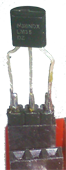
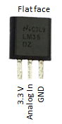
| Temperature measurement is very important in many situations, as consequence temperature sensors comes in many different flavors. In this exercise we use the LM35, a 3-pin integrated-circuit device with an output voltage that is in (almost) linear relation to the temperature and needs no calibration. Consult the datasheet for more information. There is no need for additional components. Just connect the 3 connecting leads as shown here. ADC in is the input pin (center) of the RaspEasy ADC port A.
The program displays the current temperature in degrees centigrade. Consider the following conversion: Since the sensor delivers a = 10 mV = 0.01 V per degrees centigrade, the output voltage is u = a * T. If the voltage u is applied to the 10-bit ADC powered with 3.3V, the digitized value returned to the program is v = u / 3.3 * 1023. So the relation between the temperature and the value returned from the ADC is v = 0.01 / 3.3 * 1023 * T = 3.1 * T. Program: [►] # RaspEasy7c.py # LM35 temperature sensor import smbus import time #from OLED1306 import OLED1306 def readData(port = 0): if port == 0: adc_address = 0x48 elif port == 1: adc_address = 0x4D rd = bus.read_word_data(adc_address, 0) data = ((rd & 0xFF) << 8) | ((rd & 0xFF00) >> 8) data = data >> 2 return data print "starting..." #oled = OLED1306() #oled.setFontSize(50) bus = smbus.SMBus(1) while True: v = readData() T = v / 3.1 print "T = %4.1f centigrades" %T # oled.setText(str(int(T + 0.5))) # rounded to int time.sleep(1) |
Experiment 9: Using a light sensor (LDR) |
|
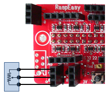
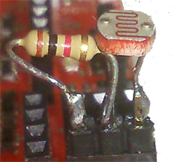
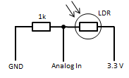
A LDR (Light Dependent Resistor) is very simple to interface. Just solder the LDR with a 1kOhm resistor to a 3 pin male header and insert it into ADC port A or B.
You have only to modify a few lines in the program RaspEasy7c.py to make your first tests. Program: [►] # RaspEasy7d.py # LDR sensor import smbus import time #from OLED1306 import OLED1306 def readData(port = 0): if port == 0: adc_address = 0x48 elif port == 1: adc_address = 0x4D rd = bus.read_word_data(adc_address, 0) data = ((rd & 0xFF) << 8) | ((rd & 0xFF00) >> 8) data = data >> 2 return data print "starting..." #oled = OLED1306() #oled.setFontSize(50) bus = smbus.SMBus(1) while True: v = readData() print "v =", v # oled.setText(str(v)) # time.sleep(0.1) |