![]()
The source code of all examples can be downloaded from here.
PWM for power control |
|
A DC (Direct Current) device is powered by a constant voltage and normally its power consumption depends on the voltage level applied. As example an electric heater can be considered as a resistor with resistance R. If U is the supply voltage, the power consumption is
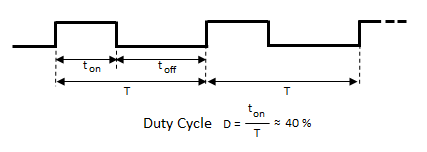
There are many electric devices that approximately behave like (variable) resistors, among them DC motors, filament lamps and LEDs. If such a device is powered by a digital output of a microcontroller system, the supply voltage level is either 0 or VCC. The voltage of a digital output port is typically VCC = 3.3V or 5V, but the device supply voltage can easily be decreased by a series resistor or increased by a simple transistor or IC driver circuit. But it is not so easy to control the power (speed of the motor, luminosity of the bulb or LED) in a purely digital system, due to the lack of analog output ports. The trick is the following: For the overall power consumption only the mean value of the supply voltage is of importance. If within a given short period T of time, say T = 50 ms, the voltage is applied only for a fraction ton of the period and turned of for the rest of the period toff = T - ton, the (mean) power is controlled by selecting the duty cycle D = ton/T (often given in percent from 0% to 100%).
It is rather easy to generate a PWM signal by software. You even don't have to write your own Python code, because a PWM generator is included in the GPIO library. Sometimes it is a too heavy burden for the processor to generate the PWM signal, then you better use a special designed external PWM chip like the PCA9685 (consult the datasheet here). | |||||||
|
|
Experiment 1: Dimming of a LED |
|
Aim: Program:[►] # PWM1.py # LED dimming import RPi.GPIO as GPIO import time P_LED = 22 # adapt to your wiring fPWM = 50 # Hz (not higher with software PWM) def setup(): global pwm GPIO.setmode(GPIO.BOARD) GPIO.setup(P_LED, GPIO.OUT) pwm = GPIO.PWM(P_LED, fPWM) pwm.start(0) print "starting" setup() duty = 0 isIncreasing = True while True: pwm.ChangeDutyCycle(duty) print "D =", duty, "%" if isIncreasing: duty += 10 else: duty -= 10 if duty == 100: isIncreasing = False if duty == 0: isIncreasing = True time.sleep(1) Remarks: |
|
|
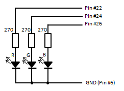
Experiment 2: Selecting the color using a 3-color LED |
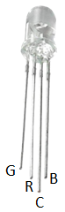
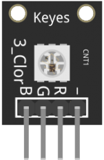
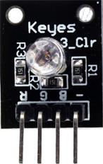
| By adding three color components R (red), G (green) and B (blue), any RGB color can be emitted (like right now on your color screen, have a look with a magnifying glass). A color LED consists of three small red, green and blue emitting LEDs mounted into a single housing. The LEDs have a common anode A (positive) or cathode C (negative) and 3 leads called R, G, B.
Common devices:
Aim: Circuitry:
Program:[►] # PWM2.py # Set RGB color import RPi.GPIO as GPIO import time import random P_RED = 22 # adapt to your wiring P_GREEN = 24 # ditto P_BLUE = 26 # ditto fPWM = 50 # Hz (not higher with software PWM) def setup(): global pwmR, pwmG, pwmB GPIO.setmode(GPIO.BOARD) GPIO.setup(P_RED, GPIO.OUT) GPIO.setup(P_GREEN, GPIO.OUT) GPIO.setup(P_BLUE, GPIO.OUT) pwmR = GPIO.PWM(P_RED, fPWM) pwmG = GPIO.PWM(P_GREEN, fPWM) pwmB = GPIO.PWM(P_BLUE, fPWM) pwmR.start(0) pwmG.start(0) pwmB.start(0) def setColor(r, g, b): pwmR.ChangeDutyCycle(int(r / 255 * 100)) pwmG.ChangeDutyCycle(int(g / 255 * 100)) pwmB.ChangeDutyCycle(int(b / 255 * 100)) print "starting" setup() while True: r = random.randint(0, 255) g = random.randint(0, 255) b = random.randint(0, 255) print r, g, b setColor(r, g, b) time.sleep(0.2) Remarks: |
|
|
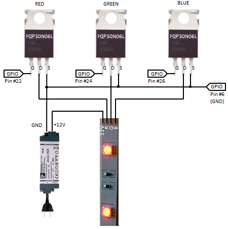
Experiment 3: RGB LED strips with MOSFET driver |
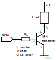
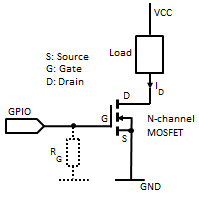
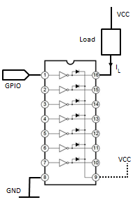
| RGB LED strips are composed by an array of color LEDs (mostly type SMD 5050). Normally 3 LEDs of the same color and a current limiting resistors are in series and driven with 12V DC. Several such elements are wired in parallel and the total current depends on the length of the strip, but may easily reach 1 A for each color input lead. This is far more than a GPIO output can deliver. Therefore some kind of buffer or driver device is needed that handles the 12V/1A supply. Commonly the driver is built with bipolar transistors or MOSFETs. Pairs of transistors can also be arranged in a IC package called Darlington array.
Common GPIO drivers:
Aim: Circuitry: As first approach you may use the same program as above, but it's up to you to create a much better performance. |
||||||||||||||||
|
|
Experiment 4: Fully addressable RGB LED strip |
|
(to be done) |
|